In the past, we had discussed BER for BPSK in flat fading Rayleigh channel. In this post, lets discuss a frequency selective channel with the use of Zero Forcing (ZF) equalization to compensate for the inter symbol interference (ISI). For simplifying the discussion, we will assume that there is no pulse shaping at the transmitter. The ISI channel is assumed to be a fixed 3 tap channel.
Transmit symbol
Let the transmit symbols be modeled as


For simplicity, lets assume that the transmit pulse shaping filter is not present, i.e 
So the transmit symbols can be modeled by the discrete time equivalent


Figure: Transmit symbols
Channel Model
Lets us assume the channel to be a 3 tap multipath channel with spacing

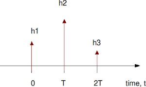
Figure: Channel model (3 tap multipath)
In addition to the multipath channel, the received signal gets corrupted by noise 
mean 
variance 
The received signal is


Zero Forcing Equalization
Objective of Zero Forcing Equalization is to find a set of filter coefficients 

After equalization

Note:
The term 
Deriving the equalization coefficients
From the post on toeplitz matrix,we know that convolution operation can be represented as matrix multiplication.
% Matlab code for using Toeplitz matrix for convolution
clear all
x = [1:3];
h = [4:6];
xM = toeplitz([x zeros(1,length(h)-1) ], [x(1) zeros(1,length(h)-1) ]);
y1 = xM*h';
y2 = conv(x,h);
diff = y1'-y2
diff = [  0   0   0   0   0 ]
Using similar matrix algebra and assuming that the coefficients

Solving for

If we assume that

Solving for

Example
% Assuming a 3 tap channel as follows
ht = [0.2 0.9 0.3];
L = length(ht);
kk = 1;
hM = toeplitz([ht([2:end]) zeros(1,2*kk+1-L+1)], [ ht([2:-1:1]) zeros(1,2*kk+1-L+1) ]);
d  = zeros(1,2*kk+1);
d(kk+1) = 1;
c  = [inv(hM)*d.'].';
The frequency response of the channel 
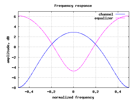
Figure: Frequency response of the channel and the equalizer
Simulation Model
Click here to download: Matlab/Octave script for computing BER for BPSK with 3 tap ISI channel with Zero Forcing Equalization
The attached Matlab/Octave simulation script performs the following:
(a) Generation of random binary sequence
(b) BPSK modulation i.e bit 0 represented as -1 and bit 1 represented as +1
(c) Convolving the symbols with a 3-tap fixed fading channel.
(d) Adding White Gaussian Noise
(e) Computing the equalization filter at the receiver – the equalization filter is 3, 5, 7, 9 taps in length
(f) Demodulation and conversion to bits
(g) Counting the number of bit errors
(h) Repeating for multiple values of Eb/No
The simulation results are as shown in the plot below.

Figure: BER plot for BPSK in a 3 tap ISI channel with Zero Forcing equalizer
Observations
1. Increasing the equalizer tap length from 3 to 5 showed reasonable performance improvement.
2. Diminishing returns from improving the equalizer tap length above 5.
3. The results are poorer compared to the AWGN no multipath results. This is due to the noise amplification (see the frequency response above) by the zero forcing equalization filter.
Next step is to discuss the zero forcing equalizer in the presence of transmit pulse shaping and then move on to minimum mean square error equalizer.
Related posts:
- BER for BPSK in ISI channel with MMSE equalization
- Using Toeplitz matrices in MATLAB
- Polyphase filters for interpolation


Generated by BlogIt
BlogIt - Auto Blogging Software for YOU!


 we would want to find a set of coefficients
  , i.e.
 ,
, is the error at sample time
  is column vector of dimension
  storing the equalization coefficients,
 is column vector of dimension
  is the number of taps in the equalizer,
 is the cross correlation between received sequence and input sequence ,
 is the cross correlation between received sequence and input sequence and
 is the auto-correlation of the received sequence.
 .
. .
. ,
,
 is the variance of the input signal
 (as there is no correlation between input signal and noise)


